ZWART APPS / ESP32 / BUILD · LEARN · SHARE

ESP32 starter kit: unboxing and component guide

A hands-on tour of the ESP32 starter kit, with components, uses, safety notes and an unboxing video.

YOUTUBE

The unboxing

A first look at the hardware and what each part is for.

THE HARDWARE

What comes in the kit

A practical identification guide based on the photographed components.

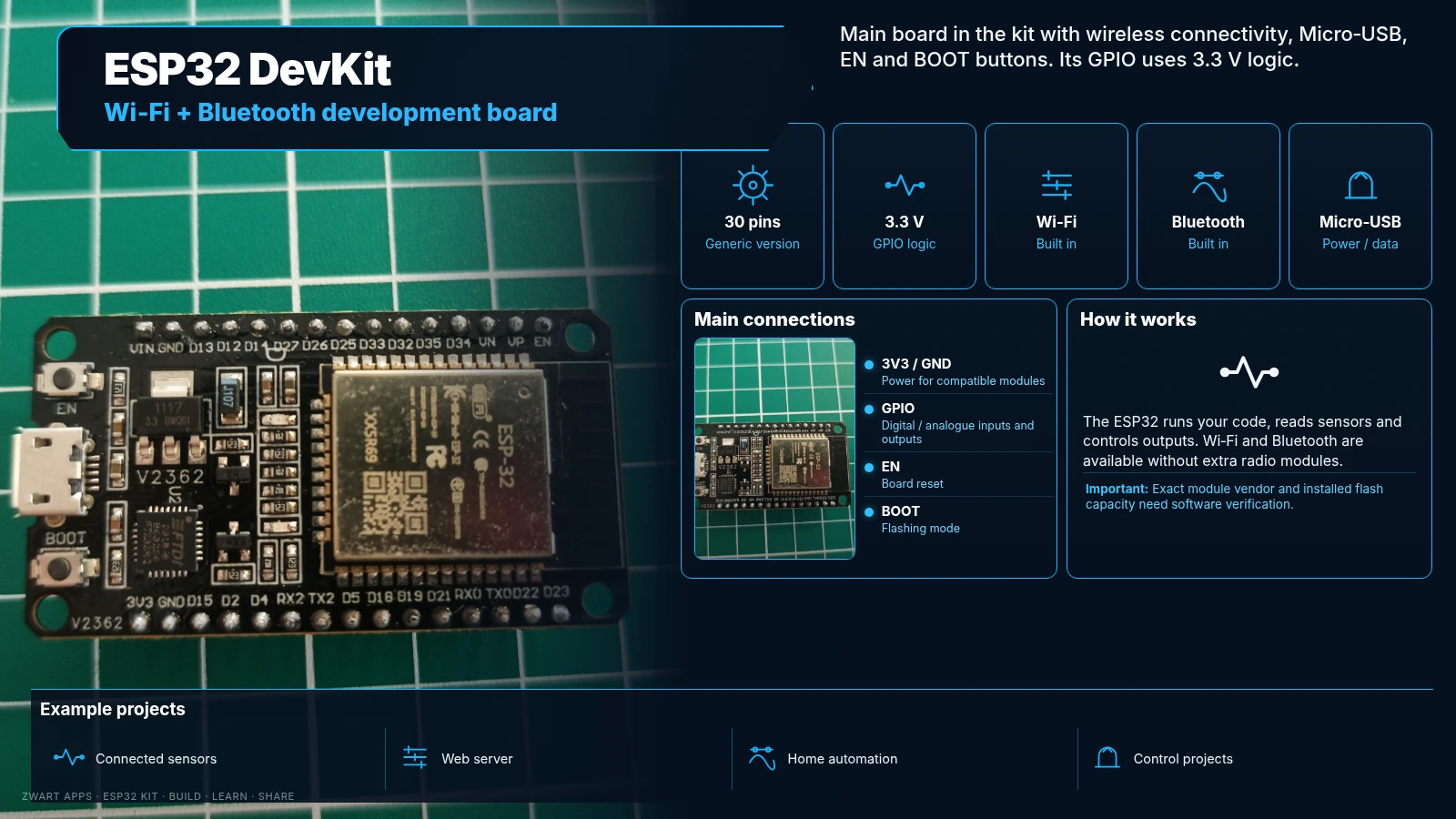
ESP32 DevKit

ESP32 DevKit

Main development board with Wi-Fi, Bluetooth, Micro-USB, EN and BOOT buttons.

How it works

Generic 30-pin version. EN resets the board and BOOT helps enter flashing mode. GPIO uses 3.3 V logic.

Example projects

Home automation, connected sensors, web servers and control projects.

Important: The shield is marked ESP-32; exact module vendor and flash capacity need software verification.
PIR motion sensor

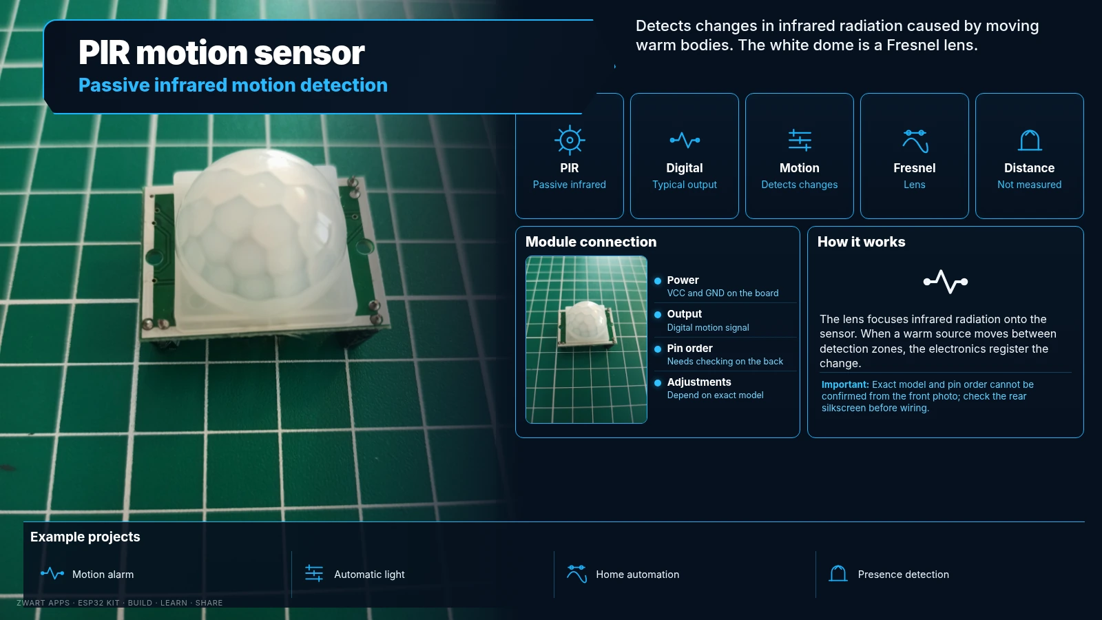
PIR motion sensor

Detects changes in infrared radiation caused by moving warm objects.

How it works

The white dome is a Fresnel lens. Output is typically digital: it signals motion but does not measure distance.

Example projects

Motion alarms, automatic lights and home automation.

Important: Exact model and pin order need checking on the back.

DHT11 sensor

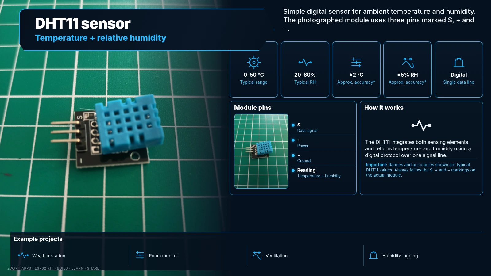
DHT11 sensor

Measures ambient temperature and relative humidity.

How it works

Typical range: 0–50 °C and 20–80% relative humidity; typical accuracy around ±2 °C and ±5% RH. Single digital data line.

Example projects

Weather station, ambient monitor and ventilation control.

Important: Check S, + and − pin markings before wiring.

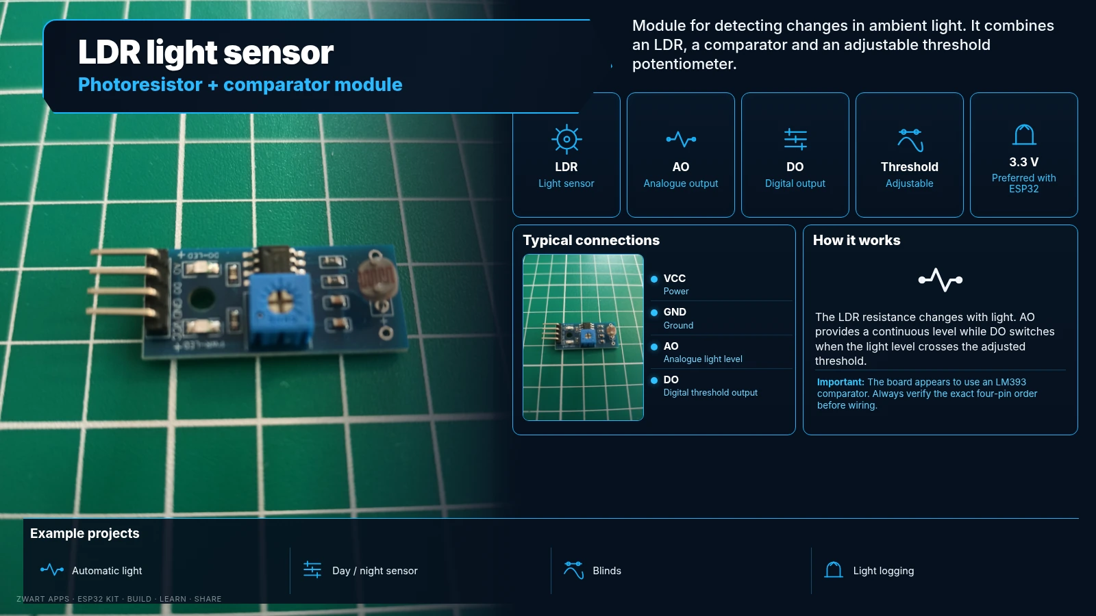
LDR light sensor

LDR light sensor

Detects changes in ambient light using a photoresistor.

How it works

Likely LM393 comparator module with analogue AO and digital DO outputs plus a threshold adjustment potentiometer.

Example projects

Automatic lights, blinds and lighting control.

Important: Prefer 3.3 V with ESP32 and verify the four-pin order.

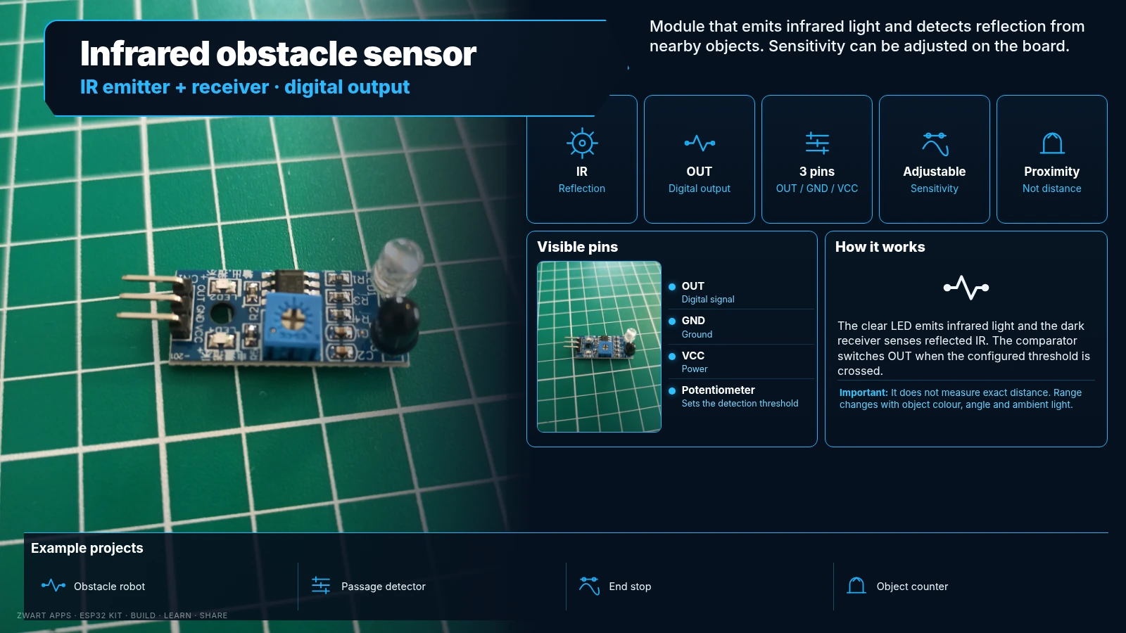
Infrared obstacle sensor

Infrared obstacle sensor

Emits infrared light and senses reflection from nearby objects.

How it works

Includes a clear IR emitter, dark receiver, sensitivity adjustment and digital OUT. Range depends on surface and ambient lighting.

Example projects

Obstacle-avoiding robots and object detection.

Important: Does not measure exact distance. Visible pins: OUT, GND and VCC.

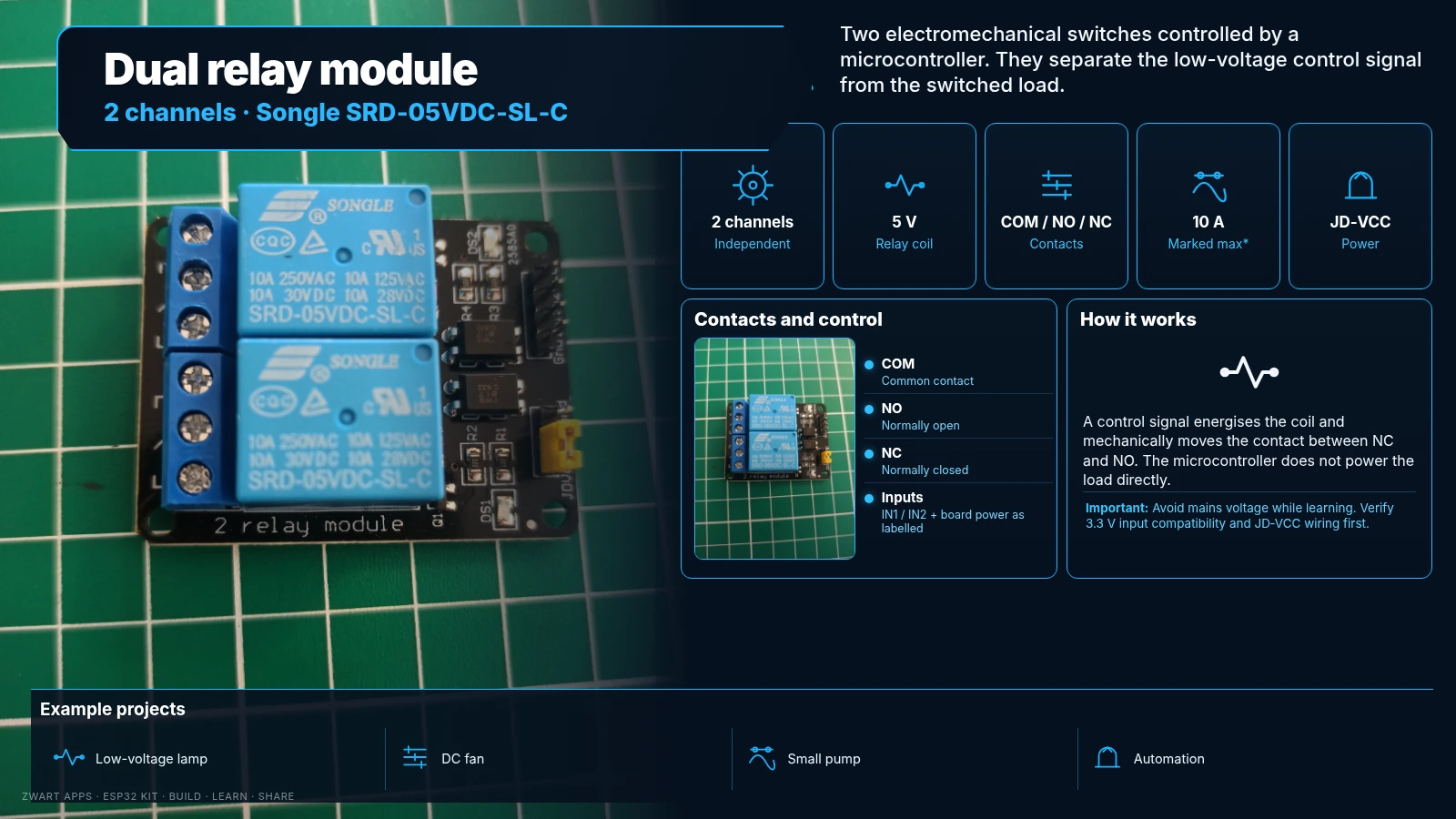
Dual relay module

Dual relay module

Two electromechanical switches controlled by a microcontroller.

How it works

Songle SRD-05VDC-SL-C 5 V coils; COM, NO and NC contacts per channel. Contact ratings marked up to 10 A depending on load and conditions.

Example projects

Switch low-voltage loads and build automation projects.

Important: Avoid mains power as a beginner. Check 3.3 V input compatibility and JD-VCC wiring.

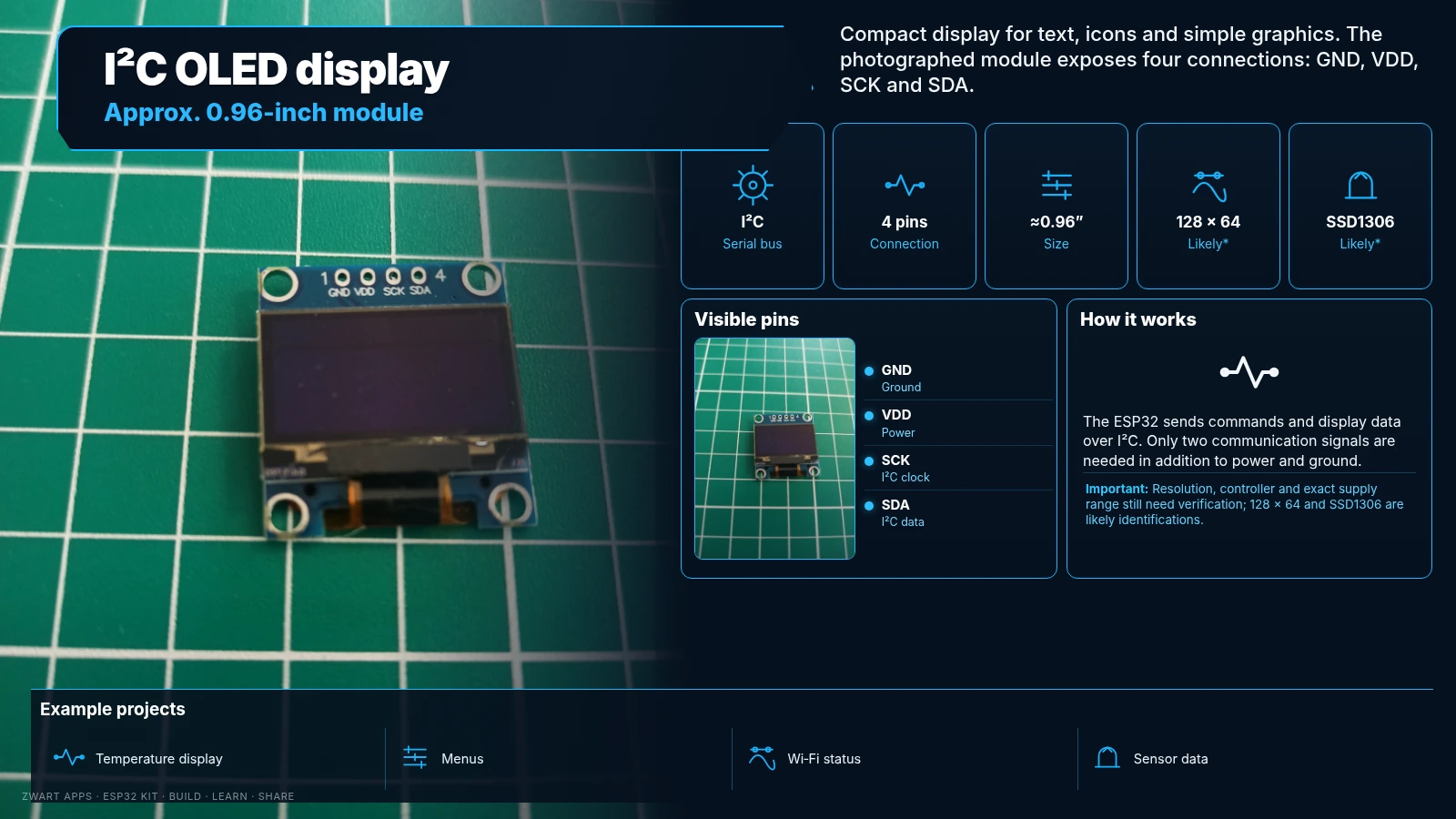
I²C OLED display

I²C OLED display

Small display for text, icons and simple graphics.

How it works

Approximately 0.96-inch module, likely 128 × 64 pixels with SSD1306 or compatible controller. GND, VDD, SCK (I²C clock) and SDA.

Example projects

Display temperature, humidity, menus and status.

Important: Resolution, controller and exact supply range still need checking.

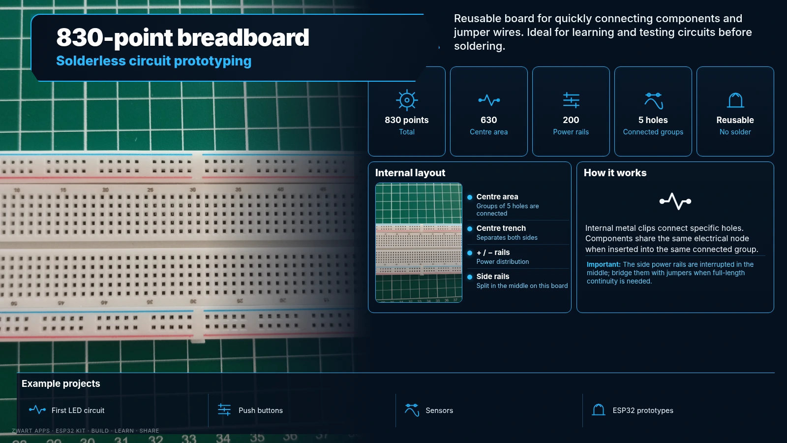
830-point breadboard

830-point breadboard

Reusable solderless board for prototyping circuits.

How it works

630 centre tie points and 200 power-rail points. Each group of five centre holes is internally connected.

Example projects

First circuits, LED and sensor prototypes.

Important: Side power rails are split in the middle; bridge them if needed.

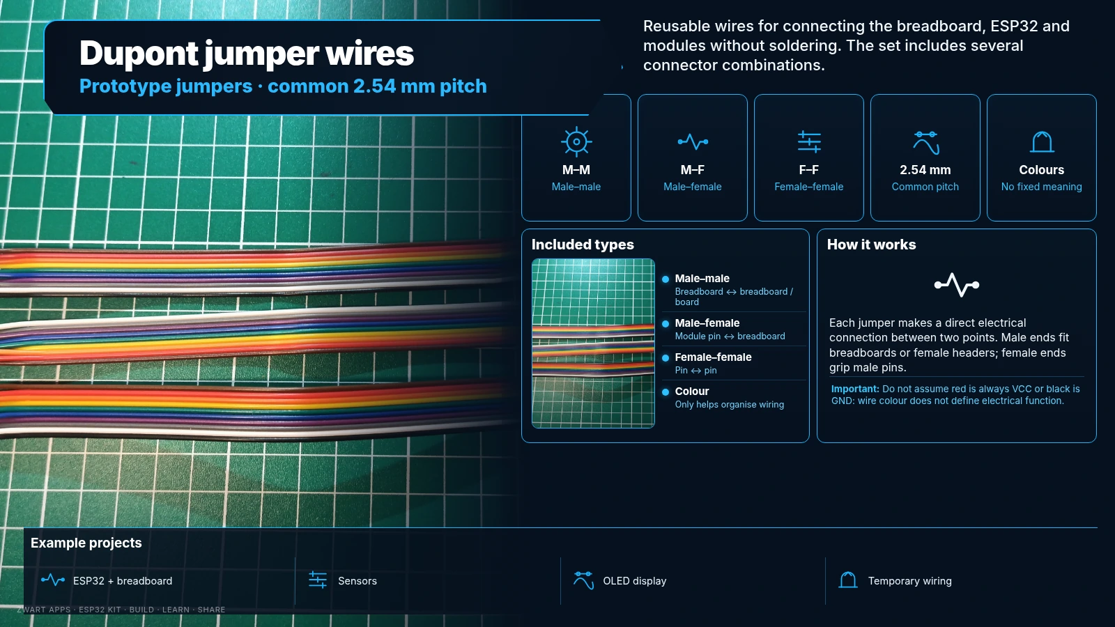
Dupont jumper wires

Dupont jumper wires

Reusable wires for joining breadboards and modules.

How it works

Three types: male–male, male–female and female–female; common 2.54 mm pitch connectors.

Example projects

Quick solderless prototype wiring.

Important: Wire colour does not determine its electrical function.

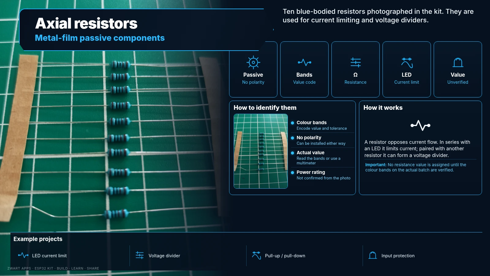
Resistors

Resistors

Passive components for limiting current and dividing voltage.

How it works

The photo shows ten blue-bodied axial resistors, likely metal-film types. Their resistance is read from colour bands.

Example projects

Limit LED current and build voltage dividers.

Important: Ohmic value and wattage unconfirmed. Illustration shows 220 Ω as an example, not a verified kit value.

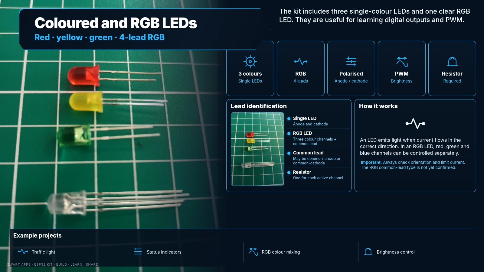
Coloured and RGB LEDs

Coloured and RGB LEDs

Three single-colour LEDs and one clear four-lead RGB LED.

How it works

Red, yellow and green LEDs have two leads; the RGB LED has three colour channels and a common lead. It may be common-anode or common-cathode.

Example projects

Indicators, traffic lights, signals and dimming.

Important: Each channel needs current limiting. Illustration is indicative; check the actual four RGB leads.

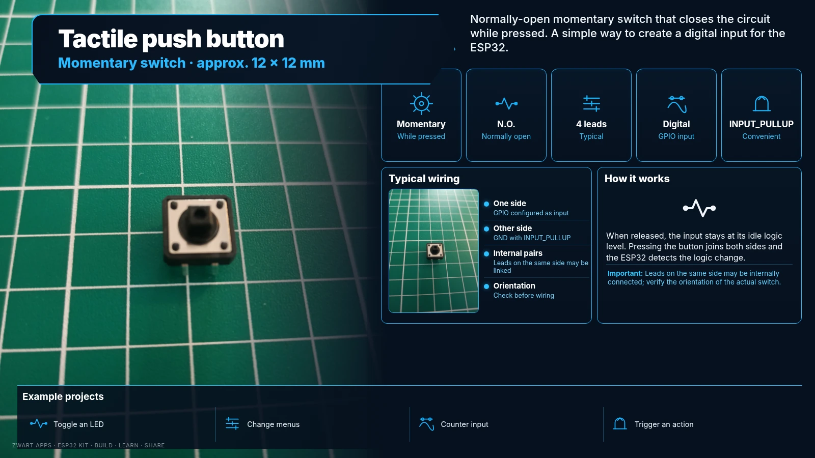
Tactile push button

Tactile push button

Momentary switch that closes the circuit while pressed.

How it works

Approximately 12 × 12 mm, normally open, usually four leads. Can use INPUT_PULLUP between GPIO and GND.

Example projects

Toggle LEDs, change menus or trigger functions.

Important: Leads on the same side may be internally connected; check orientation.

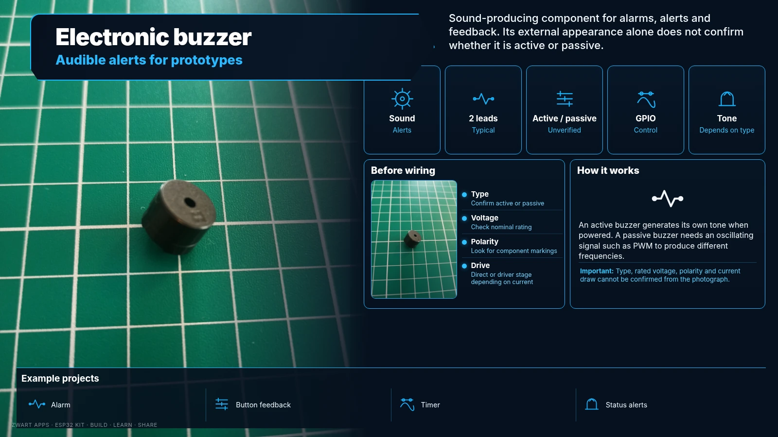
Electronic buzzer

Electronic buzzer

Produces audible alerts and sound signals.

How it works

An active buzzer sounds when powered; a passive buzzer needs an oscillating signal and can play different tones.

Example projects

Alarms, alerts and button feedback.

Important: Active/passive type, voltage and current draw remain unverified.

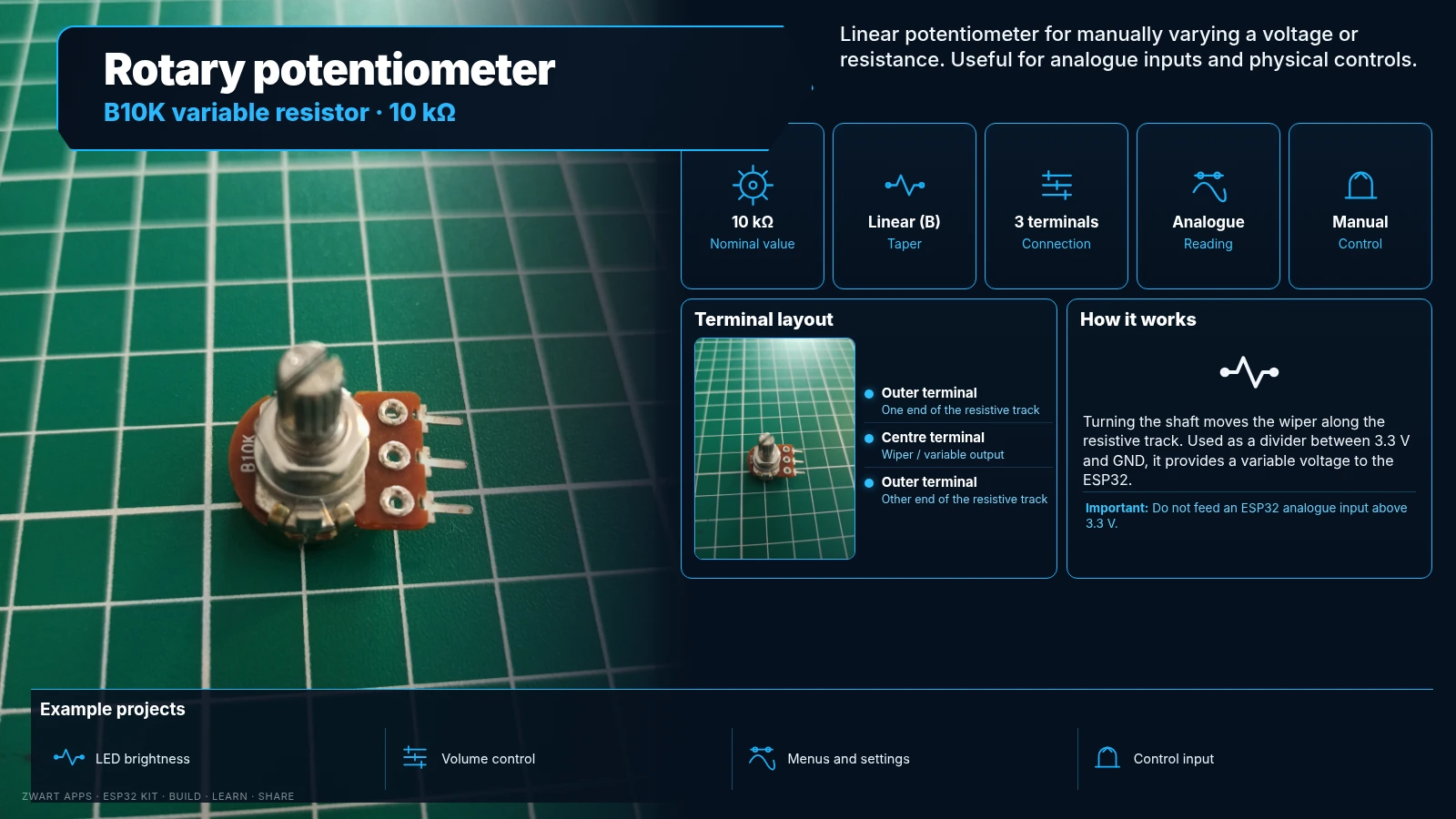
B10K potentiometer

B10K potentiometer

10 kΩ linear variable resistor with a rotating shaft.

How it works

The outer terminals form a roughly 10 kΩ track; the middle lead is the wiper. Between 3.3 V and GND it produces a variable analogue voltage.

Example projects

Brightness control, menus and manual adjustments.

Important: Do not feed an ESP32 analogue input above 3.3 V.

NEXT STEPS

From unboxing to first circuit

Start with an LED and resistor, then a button, a sensor and the OLED display. Power the ESP32 from USB and use 3.3 V logic for GPIO.

Electronics learning journey →