
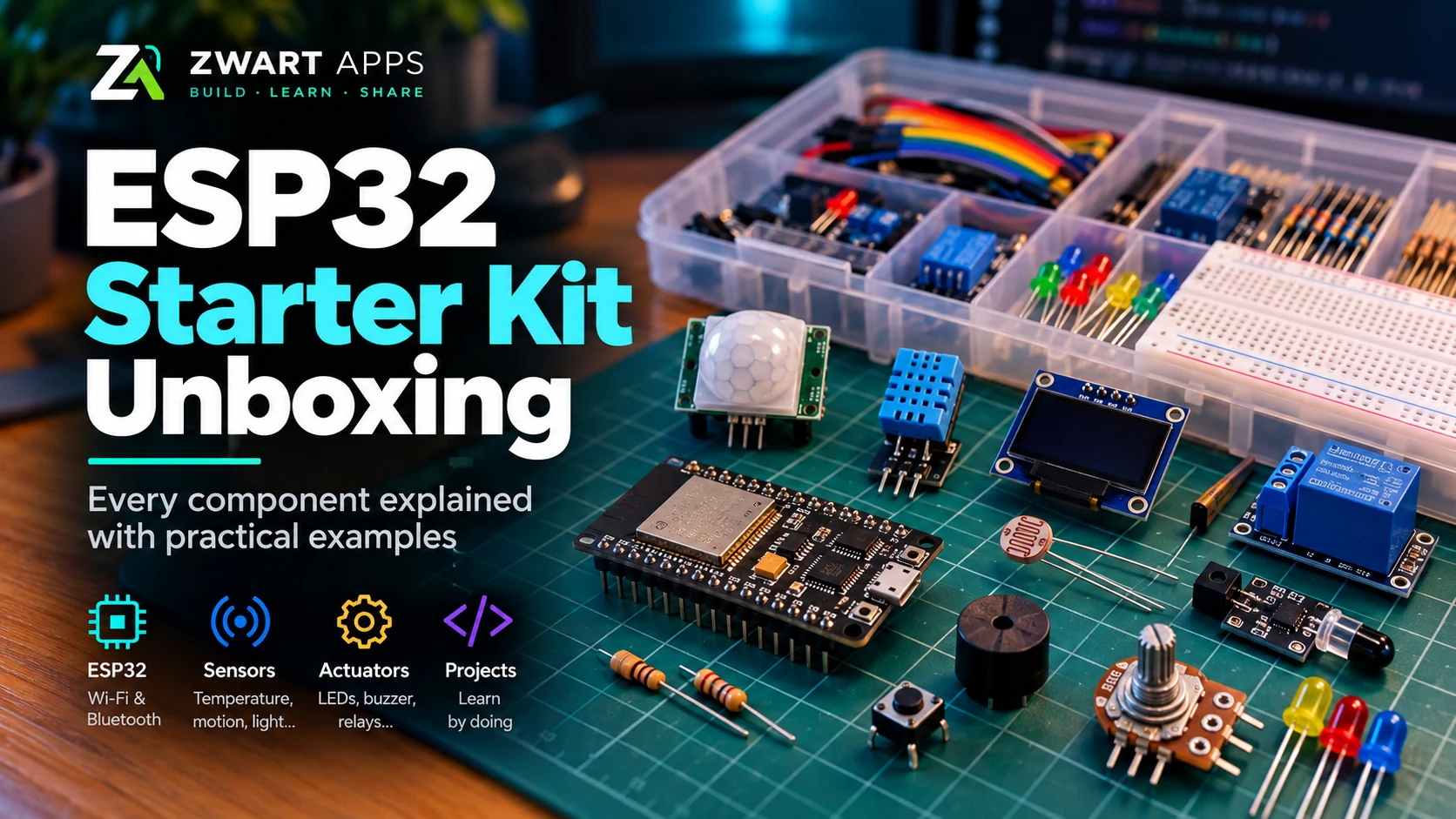
We unpack the ESP32 starter kit and explain how each part works, with practical examples and safety notes.
Watch the ESP32 unboxing
What is included in my actual kit?
This is a visual inventory of the parts I photographed during the unboxing. It is not a generic starter-kit shopping list.
ESP32 DevKit
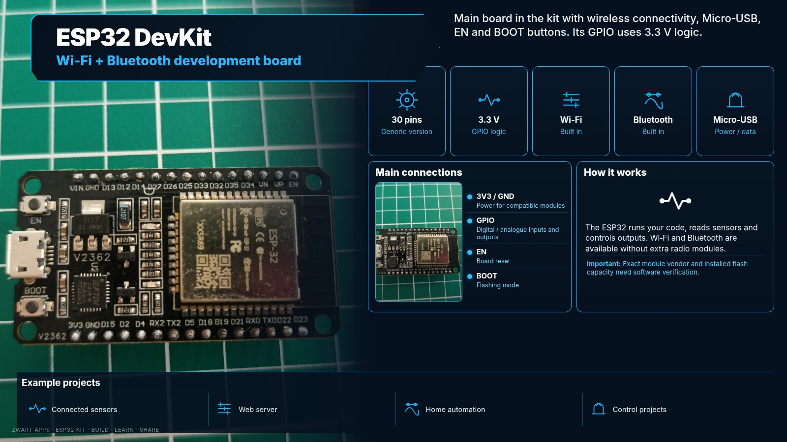
Main development board with Wi-Fi, Bluetooth, Micro-USB, EN and BOOT buttons.
Generic 30-pin version. EN resets the board and BOOT helps enter flashing mode. GPIO uses 3.3 V logic.
Projects: Home automation, connected sensors, web servers and control projects.
Note: The shield is marked ESP-32; exact module vendor and flash capacity need software verification.
PIR motion sensor
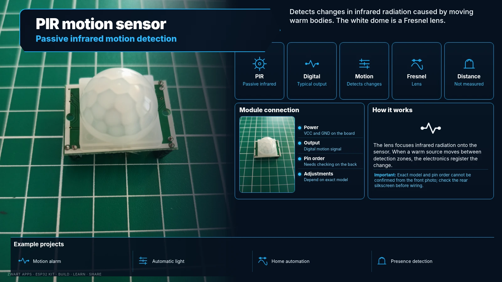
Detects changes in infrared radiation caused by moving warm objects.
The white dome is a Fresnel lens. Output is typically digital: it signals motion but does not measure distance.
Projects: Motion alarms, automatic lights and home automation.
Note: Exact model and pin order need checking on the back.
DHT11 sensor
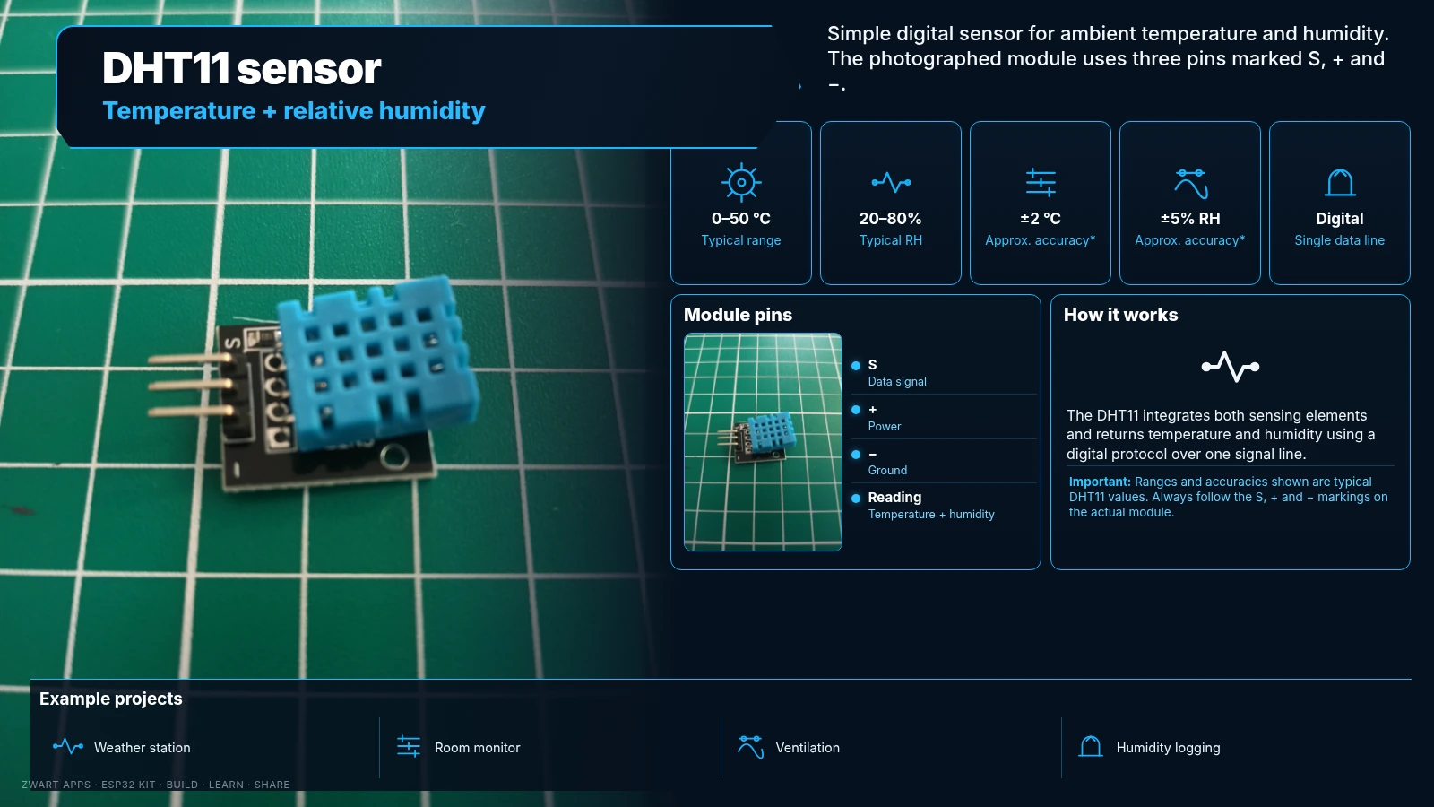
Measures ambient temperature and relative humidity.
Typical range: 0–50 °C and 20–80% relative humidity; typical accuracy around ±2 °C and ±5% RH. Single digital data line.
Projects: Weather station, ambient monitor and ventilation control.
Note: Check S, + and − pin markings before wiring.
LDR light sensor
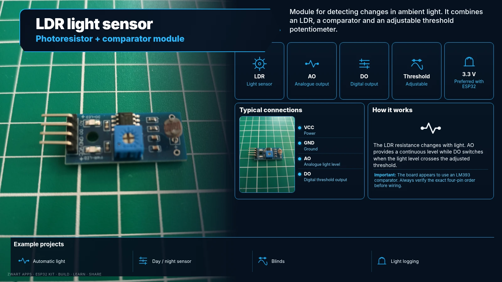
Detects changes in ambient light using a photoresistor.
Likely LM393 comparator module with analogue AO and digital DO outputs plus a threshold adjustment potentiometer.
Projects: Automatic lights, blinds and lighting control.
Note: Prefer 3.3 V with ESP32 and verify the four-pin order.
Infrared obstacle sensor
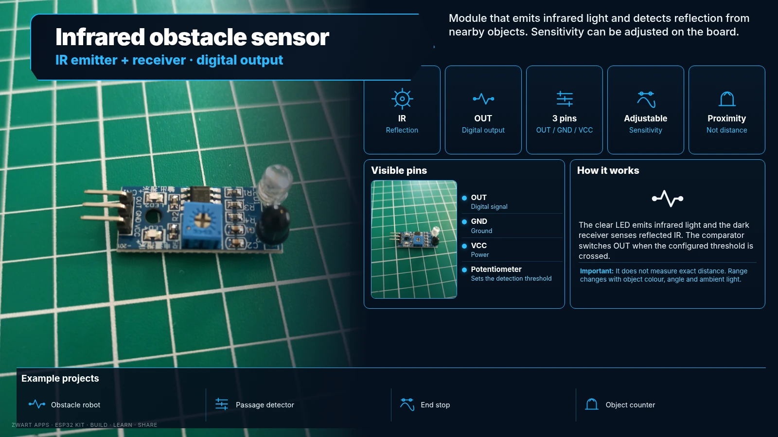
Emits infrared light and senses reflection from nearby objects.
Includes a clear IR emitter, dark receiver, sensitivity adjustment and digital OUT. Range depends on surface and ambient lighting.
Projects: Obstacle-avoiding robots and object detection.
Note: Does not measure exact distance. Visible pins: OUT, GND and VCC.
Dual relay module
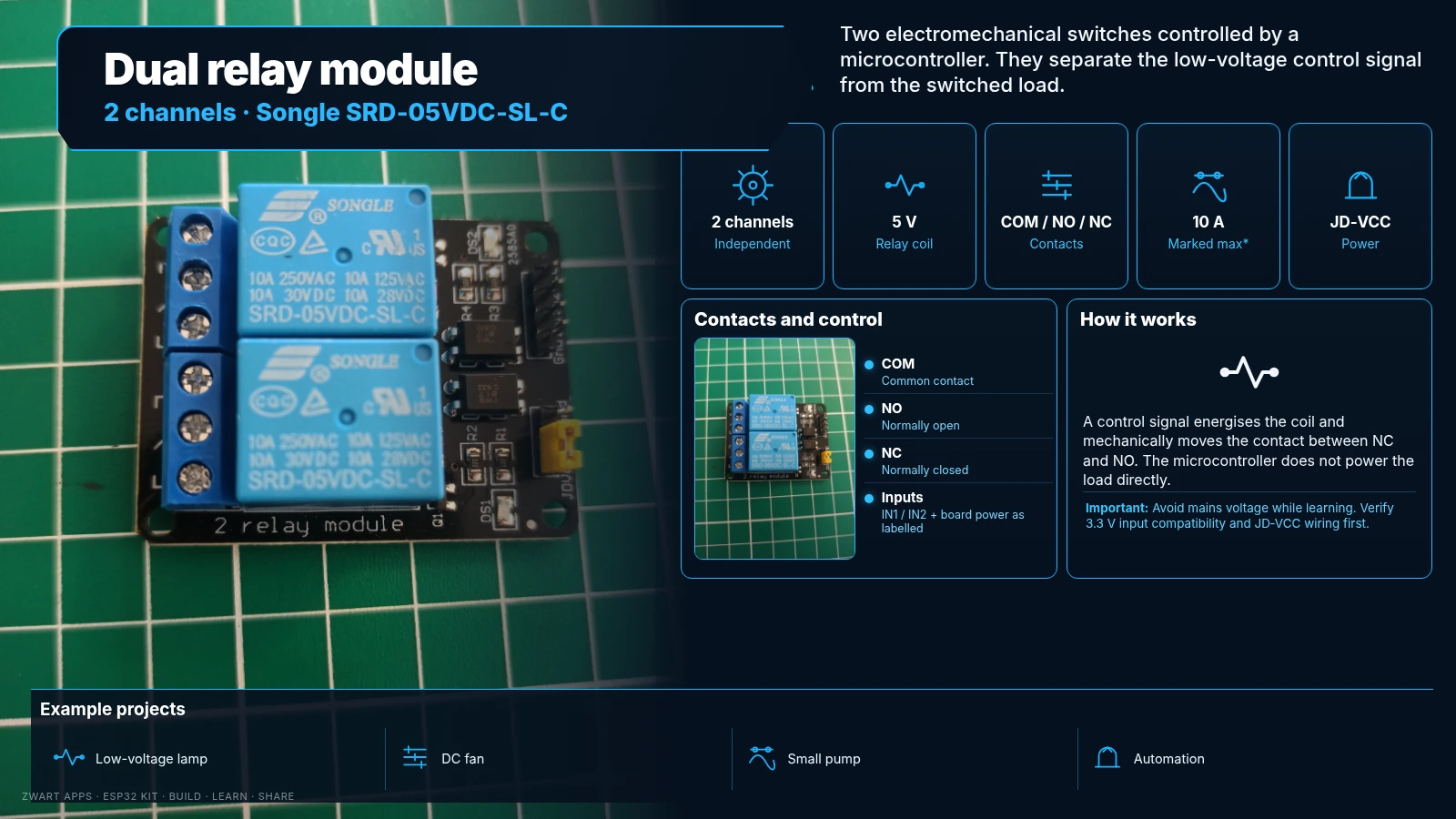
Two electromechanical switches controlled by a microcontroller.
Songle SRD-05VDC-SL-C 5 V coils; COM, NO and NC contacts per channel. Contact ratings marked up to 10 A depending on load and conditions.
Projects: Switch low-voltage loads and build automation projects.
Note: Avoid mains power as a beginner. Check 3.3 V input compatibility and JD-VCC wiring.
I²C OLED display
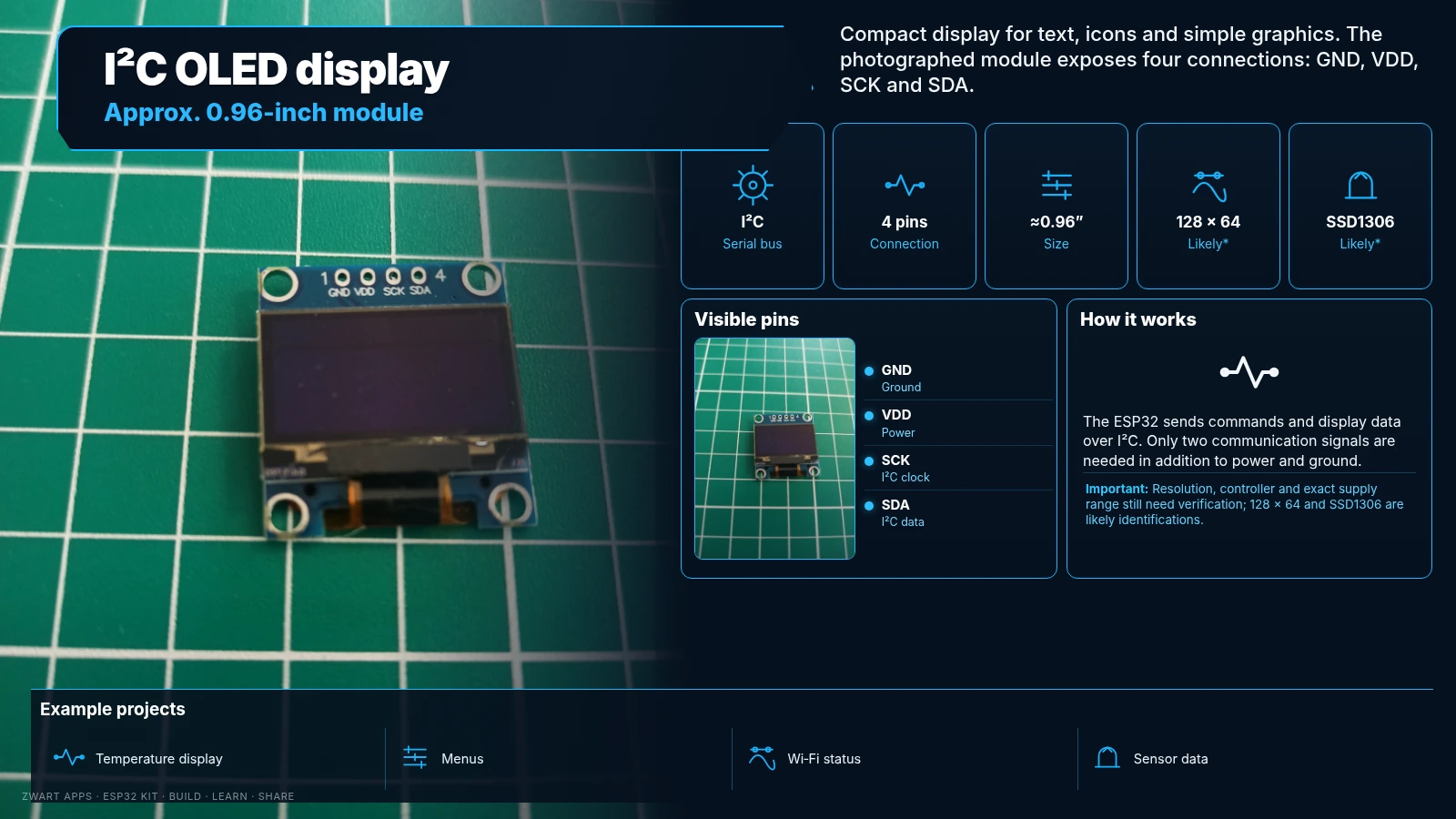
Small display for text, icons and simple graphics.
Approximately 0.96-inch module, likely 128 × 64 pixels with SSD1306 or compatible controller. GND, VDD, SCK (I²C clock) and SDA.
Projects: Display temperature, humidity, menus and status.
Note: Resolution, controller and exact supply range still need checking.
830-point breadboard
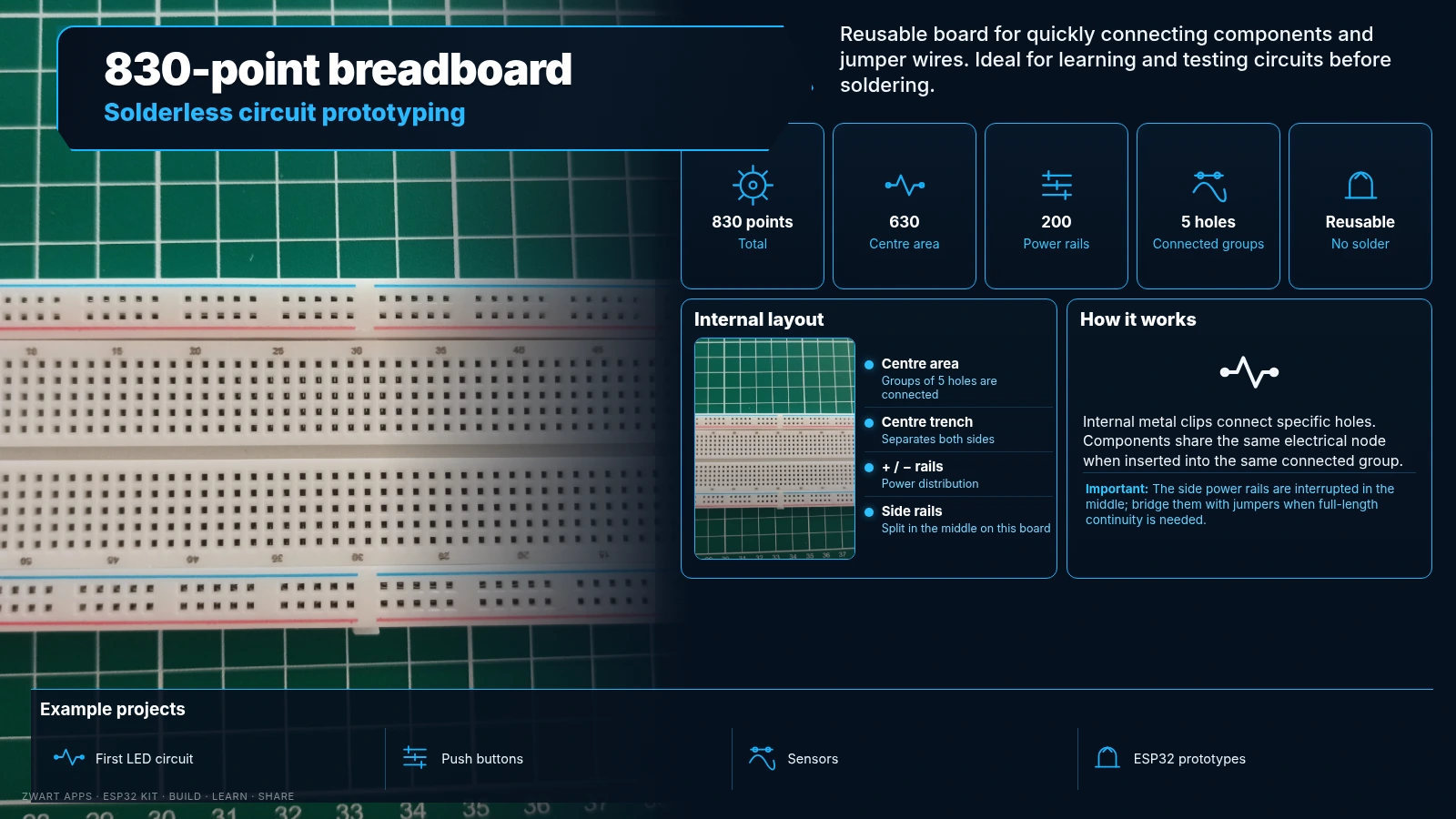
Reusable solderless board for prototyping circuits.
630 centre tie points and 200 power-rail points. Each group of five centre holes is internally connected.
Projects: First circuits, LED and sensor prototypes.
Note: Side power rails are split in the middle; bridge them if needed.
Dupont jumper wires
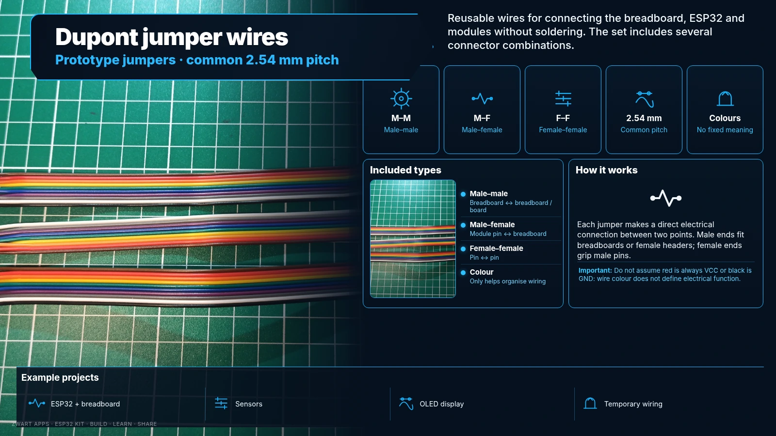
Reusable wires for joining breadboards and modules.
Three types: male–male, male–female and female–female; common 2.54 mm pitch connectors.
Projects: Quick solderless prototype wiring.
Note: Wire colour does not determine its electrical function.
Resistors
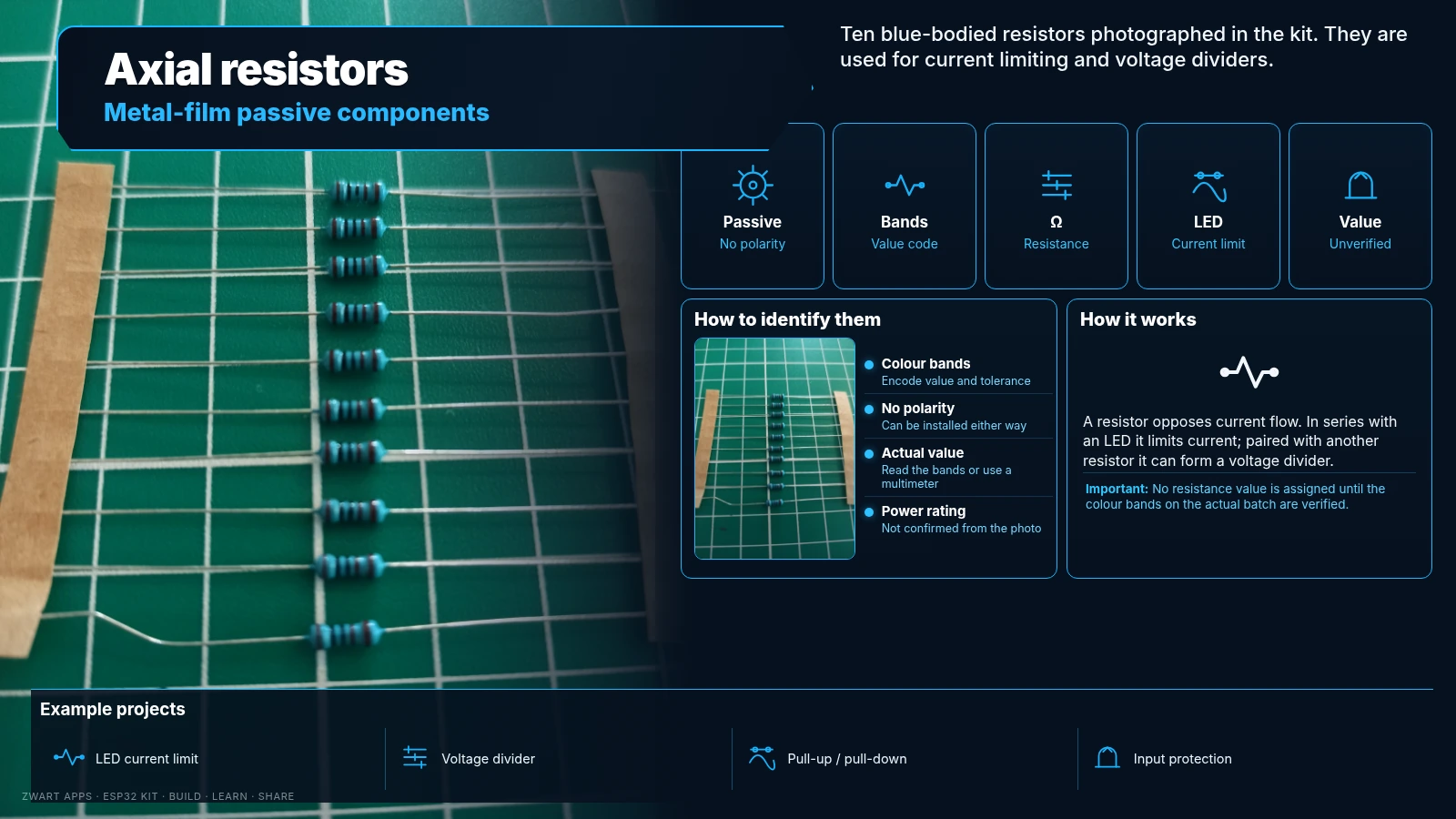
Passive components for limiting current and dividing voltage.
The photo shows ten blue-bodied axial resistors, likely metal-film types. Their resistance is read from colour bands.
Projects: Limit LED current and build voltage dividers.
Note: Ohmic value and wattage unconfirmed. Illustration shows 220 Ω as an example, not a verified kit value.
Coloured and RGB LEDs
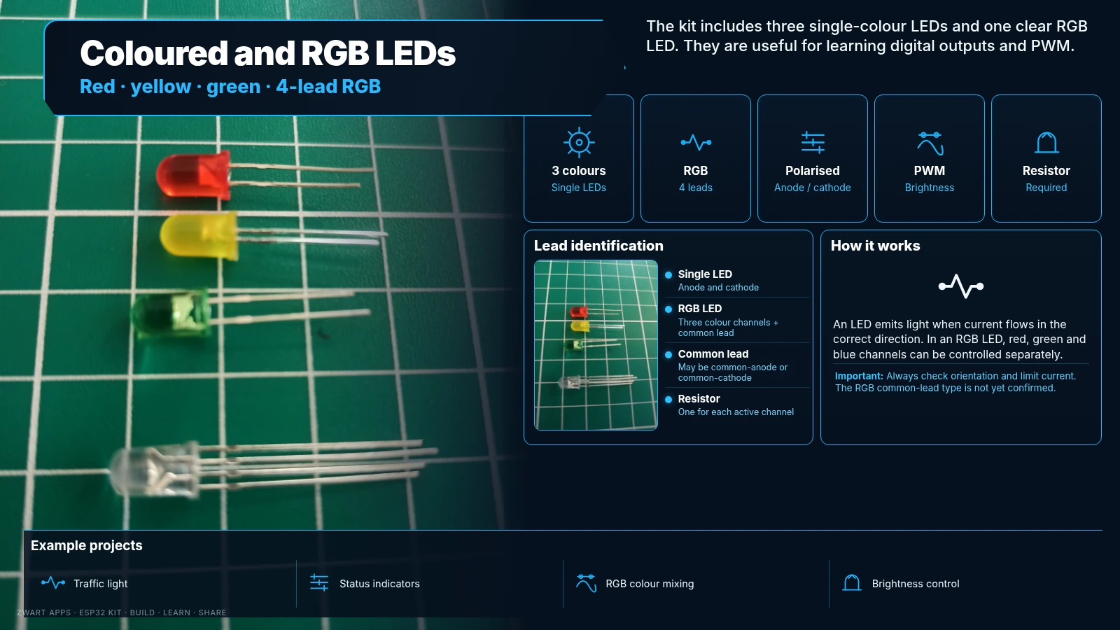
Three single-colour LEDs and one clear four-lead RGB LED.
Red, yellow and green LEDs have two leads; the RGB LED has three colour channels and a common lead. It may be common-anode or common-cathode.
Projects: Indicators, traffic lights, signals and dimming.
Note: Each channel needs current limiting. Illustration is indicative; check the actual four RGB leads.
Tactile push button
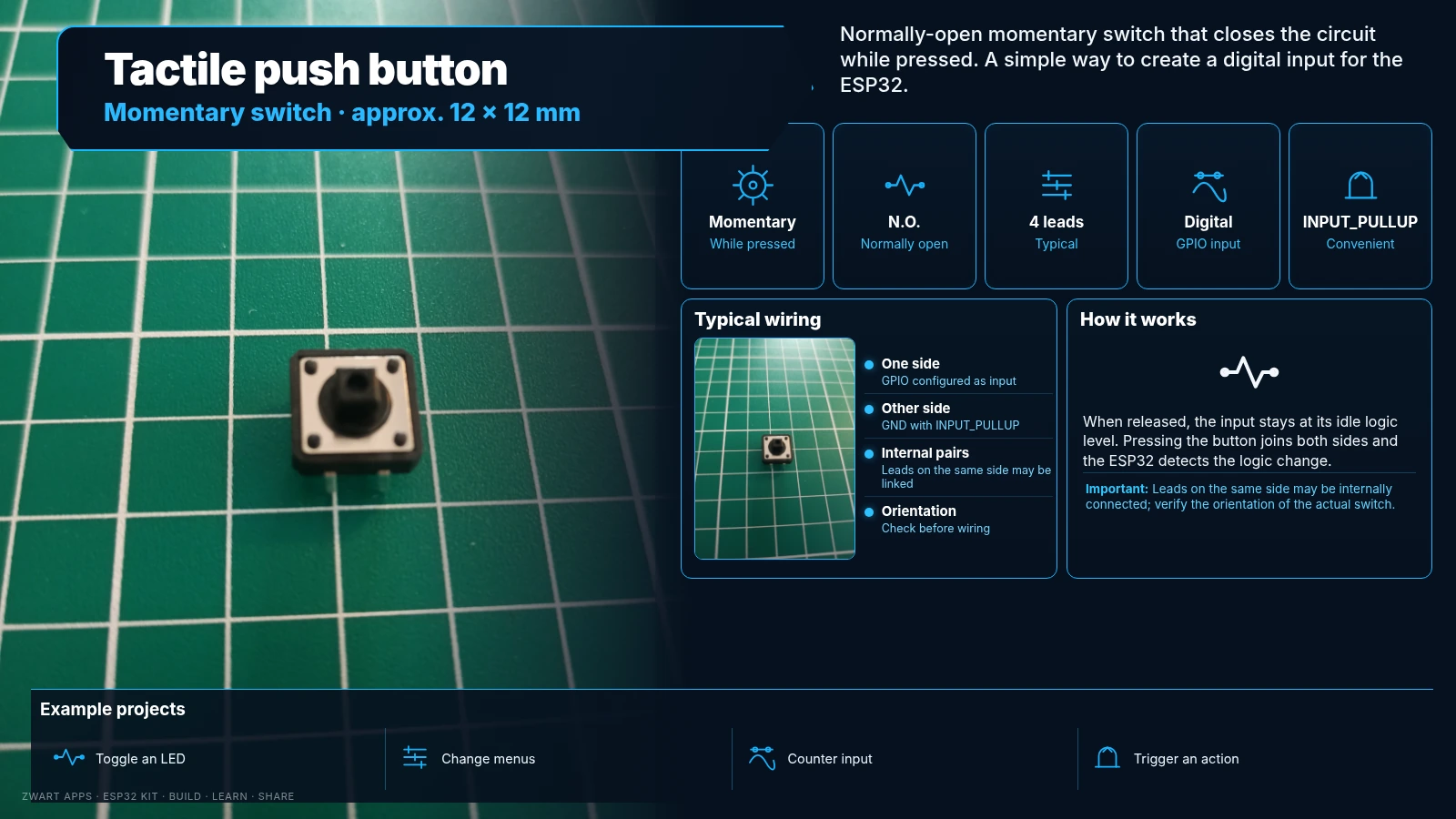
Momentary switch that closes the circuit while pressed.
Approximately 12 × 12 mm, normally open, usually four leads. Can use INPUT_PULLUP between GPIO and GND.
Projects: Toggle LEDs, change menus or trigger functions.
Note: Leads on the same side may be internally connected; check orientation.
Electronic buzzer
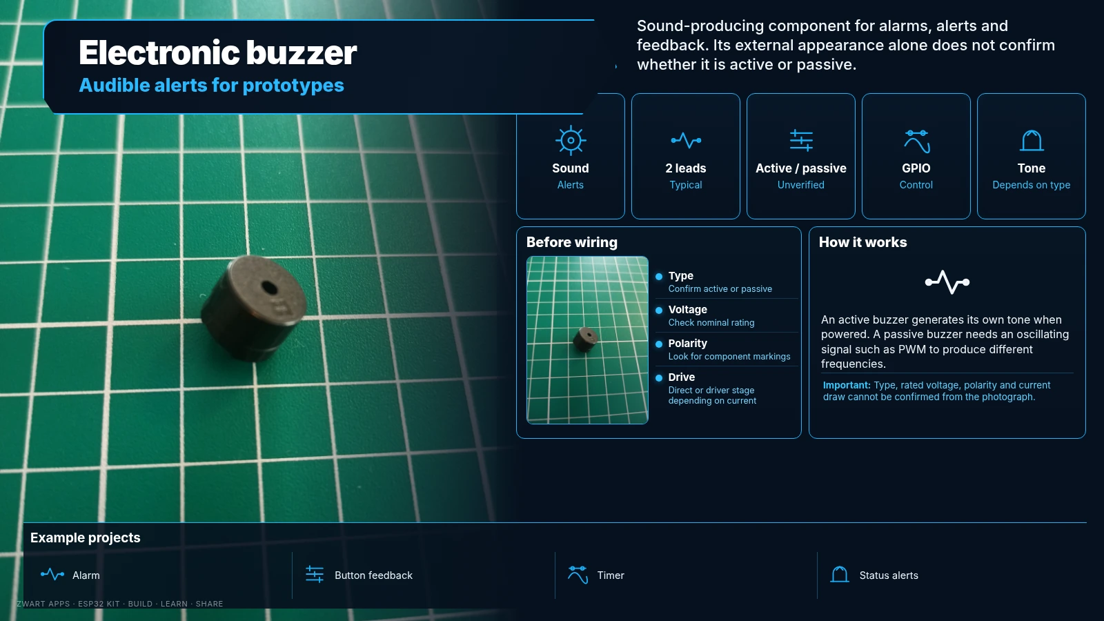
Produces audible alerts and sound signals.
An active buzzer sounds when powered; a passive buzzer needs an oscillating signal and can play different tones.
Projects: Alarms, alerts and button feedback.
Note: Active/passive type, voltage and current draw remain unverified.
B10K potentiometer
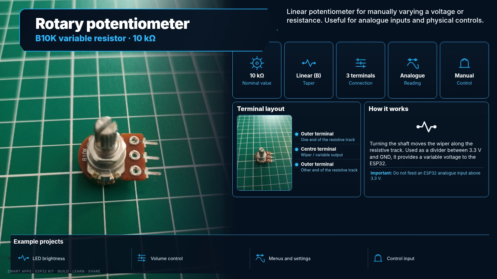
10 kΩ linear variable resistor with a rotating shaft.
The outer terminals form a roughly 10 kΩ track; the middle lead is the wiper. Between 3.3 V and GND it produces a variable analogue voltage.
Projects: Brightness control, menus and manual adjustments.
Note: Do not feed an ESP32 analogue input above 3.3 V.
Getting started safely
Start with a single LED and suitable resistor, then a button, DHT11 and OLED. ESP32 GPIO uses 3.3 V logic. Do not experiment with mains voltage on the relay module.